talk about bearing

2- BEARING material ,Bearing
damage cause
Top end bearing - Crosshead engine –
transmit load from cross head pin to connecting rod , allow relative movement
of con rod and cross head pin, Trunk pistion engine- transmit load from gudgeon
pin to con rod , allows relative movement of con rod and gudgeon pin
Bearing lubrication - Gudgeon pin and Crosshead
bearing
Fluid -film lubrication depends on the fluid's viscosity, that is, its
resistance to internal motion. This resistance is due to cohesion of the molecules within the
fluid; it occurs whenever there is internal motion, irrespective
of whether or not this motion is caused by a change in the fluid's shape. A
liquid adheres to the surface of a solid in
contact with it. The motion of the solid at the interface causes internal
motion in the liquid, which then
resists the force acting on the solid. When a shaft rotates in a journal
bearing with suitable running clearances,
resistance to motion (or 'viscous drag') carries the oil with the journal round
the bearing. The hydrodynamic conditions, that then come into operation, cause
the journal to adopt a position, relative to the bearing, in which the
running clearance on the loaded side diminishes and a high fluid pressure is
built up. Provided that the oil is delivered
to the bearing at a rate sufficient to compensate for end or side leakage, a fluid film established in this manner will
withstand severe loading. The rate at which oil escape's from a bearing depends mainly on its viscosity, the bearing
clearances and the arrangement of the oil distribution grooves. Leakage is also influenced by the condition of
the bearing and the load applied to it. Thus, by suitable bearing design and by supplying oil of the correct
viscosity at a rate above the minimum required, it is possible to maintain a lubricant film that will not rupture under
the designed running conditions. Lubrication of the gudgeon-pin bearing of trunk-piston engines is far more
difficult than that of the main, big end or thrust bearings and lubrication failure is a common cause of
trouble. Seizure of the pin can lead to bending of the connecting rod or
scuffing of the piston. The gudgeon-pin subjected to heavy loads and because of
the heat conducted from the piston, operates at relatively high temperatures.
Moreover, the small oscillatory angular motion restricts the build-up of an oil
film. In 4 stroke engines, satisfactory lubrication is promoted by cyclic lifting
of the gudgeon pin within the bearing that takes place towards the end of the
exhaust stroke. This movement, caused by
forces of inertia, accompanies reversal of the direction of load and enables
the bearing to 'breathe'. So the
clearances are refilled with oil. In the two stroke engine, there is no
'breathing',. since the bearing
load, though fluctuating is continuously downwards as in the main bearings.
Various special arrangements are therefore used to ensure satisfactory
lubrication of gudgeon pins. One method is to increase the bearing area to such an extent, that the hydraulic load due
to oil pressure is able to force the pin and journal out of contact with each
during the minimum loading period. These conditions of gudgeon-pin lubrication also apply in general to the crosshead
bearings of large, low-speed, two-stroke crosshead engines.
Owing to the oscillating movement on the bearing, it is
very difficult to establish full hydrodynamic lubrication, and conditions of boundary lubrication
usually prevail. Crosshead engines are therefore subject to local overloading and failure of the lubricant film,
leading in turn to fatigue cracking and possible break-up of the surface. Various means have been adopted to improve
lubrication of crosshead bearings. Manufacturers attempt to keep the specific loading as low as possible, for example by
a large crosshead pin diameter, and by allowing self-adjustment of the
bearing housing, to compensate for deformation of the crosshead pin and the head of the connecting rod. This flexibility
maintains a uniform load distribution. In addtion to reduced loading and
improved lubrication, other important factor in the maintenance of bearings are
the alignment between them and the surface
finish of the crosshead pin.
By providing of hydrostatic lubrication to X head bearing , such as
Fitting of reciprocating positive displacement L.O pump , utilized by movement
of con. rod , Arrange booster pump to supply X head bearing up to 16 bar.
To
combat the difficulty of Fluid -film lubrication - Sulzer engine- conjugate
deflection(crosshead pin bored at center), continuous full length bottom half
of crosshead bearing(MAN B&W), eccentric bored bearing & machining
shell (Fiat engine), large diameter stiff crosshead pin L/D ratio less( con rod
and crank throw ratio keep as low as to increase sliding velocity &
improved lub oil film), make cross head pin high degree of surface finish
<0.1 micron, thin shell bearing & improved material.
Man b&w crosshead
bearing -
The lower half of the bearing housing is formed by the top end of the
connecting rod. It supports the crosshead pin over its entire length, the
piston rod being bolted to the top half of the crosshead pin through a cut out
in the bearing top half. Oil supply to the crosshead is via a telescopic pipe
from the main LO supply at a pressure of about 2.5 bar.
Bearing
Type -The type of bearing used in the crosshead assembly is a thin
shell (insert) bearing . The lower shell is a trimetal shell, i.e. the
shell is composed of a steel back with cast-on white metal and an
overlayer coating. The upper shell is a bimetal shell, as it does
not have the overlayer coating; both the upper and lower shells are
protected against corrosion with tin flash

credit to MAN B&W service letter
Bearing Function and Configuration- Because of the oscillating
movement and low sliding speed of the crosshead bearing, the hydrodynamic
oil film is generated through special oil wedges on
either side of the axial oil
supply grooves situated in the loaded area of the bearing.
The oil film generated in this manner can be rather
thin. This makes the demands for pin surface roughness and oil wedge geometry
very important parameters for the assembly
to function. A further requirement is effective
cooling which is ensured by the transverse
oil grooves. The pin surface is superfinished. The lower shell is executed with a special
surface geometry (embedded arc) which extends over a 120 degree arc, and
ensures a uniform load distribution on the bearing surface in contact with the
pin. The lower shell is coated with an
overlayer , which enables the pin sliding geometry
to conform with the bearing surface.
In MAN B&W engines, a set of channels have been
machined in the lower crosshead bearing, in
which the cooling oil can pass. The geometry is
designed in such a way that all the loaded square centimetres of the pin are
flushed with cooling oil twice every engine cycle. In contrast, the Sulzer
crosshead has a plain lower bearing without channels. In order to inject oil
between pin and bearing, they have to supply oil at a much higher pressure. The
injection will take place at around 20 degrees crank angle before TDC, where
the cylinder pressure is still low and upward inertia forces on piston is still
high. There is a short interval, in which the bearing pressure is lower than the
oil pressure.
cosmetic wiping - this wiping is of a cosmetic
nature; but it can sometimes cause blockage of the oil-wedges that normally
build up the oil film to the "pads" inside the bearing, Disturbance of the oil film build-up inside
the bearing could result in slight fatigue damage just behind the blocked area
of the oil-wedge. If the phenomenon is observed at an early stage during
inspections. The problem is solved by removing the wiped lead from the
oil-wedge.
Sulzer RTA
96
Main bearing oil system
Main bearing oil is also used to cool the working
piston via a toggle lever at an
operating pressure of 4.0 BAR TO 4.8
bar. The main bearing and crosshead oil systems are interconnected through a
non-return valve . The integrated axial detuner, and if there is a vibration
damper as well as an electrical balancer built-on at the free end (by 6 Cyl.
engines), are supplied and cooled with bearing oil.
Should the crosshead lubricating oil pump fail, then the crosshead bearing oil system
is supplied with main bearing oil pressure. Under such conditions the engine
can only be operated at reduced load (Load Indicator Position, LIP max.
4.5).
Crosshead bearing oil system
The operating pressure of the high pressure oil is
10 to 12 bar. The lubrication of crosshead pins as well as of connecting rod
bottom end bearings is effected through toggle lever.
The oil supply for the exhaust valve actuator pumps
to the exhaust valve control passes from
the crosshead bearing oil system through the air separator . For actuating the
exhaust valves, the oil pressure is raised to about 160 bar by the actuator
pumps .The reversing servomotors on the camshaft are actuated by crosshead
bearing oil.
Main bearing – support crankshaft and keep it aligned. To
remove heat produced by friction.
Bottom end / crankpin bearing – transmit load
from con rod to crankshaft. Allow relative movement of con rod & journal.
The MC engines were originally designed with
white metal bearings for the crosshead, crankpin and main bearings. The main
bearings were of the so-called thick shell design,whereas the crosshead
and crankpin bearings were of the thin shell design.
Thin shell main bearings
The development towards higher specific engine
outputs has resulted in the gradual introduction of the thin shell design for
the main bearings. Sn40Al (tin-aluminium), which has been applied with great success
on the main bearings for the smaller two-stroke engines, has been introduced on
the S46-70MC-C engines, on which good service has been experienced .In addition
to the above, an advantage of the thin shell design is the reduced risk of
fretting-corrosion between the main bearing saddle and shell when the bearing
housing is well designed. Running-in on testbed and during sea trials has in a
number of cases caused light seizure of Sn40Al main bearing shells on the
S-MC-C engines. This seizure can be avoided either by prelubrication with
grease or high-viscosity oil, or by PTFE-coating of the running surface of the
shells. The Sn40Al bearings have been introduced on the engine with the same
well-proven specific load level as that for white metal bearings. (A thin shell
bearing design was introduced to more recent engine types. The main bearings of
the small and medium bore models (S46MC-C to S70MC-C)are lined with AlSn40 and
provided with a PTFE running-in coating as standard.
The bearings of the large bore models are lined with
white metal.)
Nip – the external circumference of
a pair of bearing shell is slightly larger than the bore of housing. This
difference is called nip.
Locating tangs - allow correct axial
positioning of bearing shells thereby ensuring alignment of oil transfer
passages and clearance between the ends of the bearing and crankshaft fillets.
The tang is located in a corresponding recess in the housing and must be a
clearance fit, otherwise the bearing surface may distort. It is also advantageous
to relieve the tang below the level of the bearing joint face, thus reducing
localized pressure on the tang during assembly. Tangs are not intended to
resist rotation of the bearing shell; that is achieved by the contact pressure.
If, under seizure conditions, this contact pressure cannot prevent rotation,
the tangs are either sheared or flattened.
Cause of thin
shell bearing shifting
– 1-defective tag or improper fitting precedure, 2-insufficient nip clearance,
3-suddenly applied extreme load(pounding), 4-incorrect size of bearing use,
5-due to overtightening bolts(elongation of bolts), 7- friction force from back
of the shell and keep. The overall thickness/diameter ratio is not critical,but
typically varies from 0.05 at 40 mm diameter to 0.02 at 400 mm
Interference fit
or bearing crush
- On assembly the excess peripheral length creates a circumferential stress
around the bearing, and a radial contact pressure between the bearing
back and the housing bore. This contact pressure
resists relative movement, thus preventing fretting. Unfortunately, there is no
theoretically correct level; housings with high flexibility require more
contact pressure than stiffer ones. On early engines, having thin shell
bearings, a contact pressure as low as 2MPa was usually sufficient to resist
fretting, but as engine ratings increased, and housing stress analysis became
more sophisticated, higher pressures became necessary, often reaching 8-10 MPa
today. In these very high interference fit assemblies, particular care has to
be taken to ensure that the joint face clamping bolts have sufficient capacity
to assemble the bearing, and to resist dynamic separating forces generated by
engine operation.( need to follow the instruction to tighting correct hydraulic
pressue at con rod bolts)
Thick shell main bearings (Optimum Lemon Shape (OLS) bearing
with flexible edges)
The design of the thick shell bearings has been
updated in order to ensure reliable performance. The major updates are
summarised in the following. Optimum Lemon Shape (OLS) shells,have been
introduced to increase the minimum oil film thickness. optimum lemon shape
(OLS)-type main bearing as an evolution of the Mark 5 bearing type, featuring
reduced top and side clearances.


credit to MAN B&W service letter
Flex –Edge thick-shell main bearing design.
SL03-414/AAB-Engine types: S/L50-80MC
Flex-Edge. Design
is fully interchangeable with previous types and provides an increased
margin against fatigue damage occurring in the edge area. There have been a few
reports of local bearing fatigue damage still occuring near the bearing shell
edges, in a few highly edge-loaded main bearing positions. New, advanced
calculations, including journal tilt and housing deformation, have provided
detailed information on the load pattern mechanisms of the main bearings. The
calculations indicate that a certain radial flexibility of the bearing edge
will
significantly increase the minimum oil film
thickness near the edges. Likewise, the maximum oil film pressure near the
edges will be reduced. The Flex-Edge design feature has been tested with
success, for more than a year, in positions which initially suffered repeated
problems.
The flexibility has been achieved by machining a 3
mm deep round-edged groove on
the back of the shell, with a width equal to the
thickness of the bearing shell, thus
avoiding contact with the bearing support in this
area. The unsupported part of the shell will flex slightly when load is
applied, thereby increasing the effective bearing area in situations where the
centrelines of the shaft and the bearing are not in alignment. A further
feature is static deformation of the unsupported part, which occurs when
tensioning the bearing housing..
Apart from the flexible edges, the properties of the
bearing are similar to those of the Optimum Lemon Shape type. This design
provides a larger safety margin in the event of geometrical
non-conformities. The deformation ensures a
controlled and smooth convex shape, 10-20 μm larger bore toward the edges.
Calculations confirm that such a shape further increases the safety margin
against high edge-loading.
Bearing
Metals
Tin
based White Metal (There is no interlayer in
white-metal based bearings)- Tin-based white
metal is an alloy with minimum 88% tin (Sn), the rest of the alloy composition
is antimony (Sb), copper (Cu), cadmium (Cd) and small amounts of other elements
that are added to improve the fineness of the grain structure and homogeneity
during the solidification process. This is important for the load carrying and
sliding properties of the alloy. Lead (Pb) content in this alloy composition is
an impurity, as the fatigue strength deteriorates with increasing lead content,
which should not exceed 0.2 % of the cast alloy composition. The fatigue strength of the basic
white metal composition can be increased by adding
cadmium, which goes into solution
in the matrix, and by adding trace quantities (0.1
per cent) of chromium, which refines the distribution of the copper-tin
compound. Tin based white metal is used in the main bearings, crankpin
bearings, crosshead guide shoes,
camshaft bearings and thrust bearings because of its
excellent load carrying and sliding properties.
Tin
Aluminium (AlSn40)-
In AlSn40 bearings, the overlayer is always bonded to the bearing
metal by a very thin interlayer of Ni (nickel), or Ag (silver).
Tin aluminium is a composition of aluminium (Al) and tin (Sn) where the tin is
trapped in a 3-dimensional mesh of aluminium. AlSn40 is a composition with 40%
tin. The sliding properties of this composition are very similar to those of
tin based white metal but the loading capacity of this material is higher than
tin based white metals for the same
working temperature; this is due to the ideal combination of tin and
aluminium, where tin gives the good embedability and sliding properties,
while the aluminium mesh functions as an effective load absorber.Tin
aluminium is used in main bearings
and crosshead bearing lower shells.
Overlayers
- An overlayer is a thin galvanic coating of mainly lead (Pb) and tin
(Sn), which is applied directly (on to the white metal ) or,( via an
intermediate layer, on to the tin aluminium sliding surface of the bearing). The
overlayer is a soft and ductile coating, its main objective is to ensure good
embedability and conformity between the bearing sliding surface and the pin
surface geometry.
Flash
layer, Tin (Sn) - A flash layer is a 100% tin (Sn) layer which
is applied galvanically; the thickness of this layer is from 2 µm to 5 µm. The
coating of tin flash is applied all over and functions primarily to prevent
corrosion (oxidation) of the bearing. The tin flash also functions as an
effective dry lubricant when new bearings are installed and the engine is barred.

credit to diesel engine reference book
copper-tin-lead alloy bearing (lead
– bronze alloy ).
lead-bronze bearing linings were introduced when fatigue of white metal became
a serious problem. They are used in very highly loaded bearings because of
their high fatigue strength; their drawback is poor tribological
behaviour. That is why they require an electroplated
overlay in most applications. It is always overlay-plated, primarily to protect
the lead phase from corrosion but also because the alloy is relatively hard and
incompatible. Standard composition for con-rod and main bearings is 78 % Cu, 20
% Pb, 2 % Sn. The alloy is used with electroplated overlay or cast babbit
running layer
These bearings can be found in marine diesel medium
speed engines.
Material
|
Maximum loading
(MPa)
|
|
AlSn6Cu1Ni1
|
Aluminium alloys:
|
38
|
CuPb26Sn1.5
|
Lead-bronze alloys:
|
38
|
AlSn20Cu1
|
Aluminium alloys:
|
35
|
AlSn40Cu0.5
|
Aluminium alloys:
|
20
|
SnSb8.5Cu3.5Cd1Cr0.1
|
White
metal alloy
|
14
|
SnSb7.5Cu3.3
|
White metal alloy
|
12
|
PbSb 10Sn6
|
White metal alloy
|
12
|
General Bearing Requirements and
Design Criteria
Bearings are vital engine
components; therefore, the correct bearing design and the proper choice of
bearing metal is necessary for reliable engine performance. Bearing design
criteria depend on the bearing type and, in general, on:a) Bearing sliding surface
geometry.b) The surface roughness of
the journal or pin, which determines the permissible bearing pressure and
required oil film thickness. This is necessary to ensure effective and safe
functioning of the bearing.c) The correct flow of cooling oil to prevent heat
accumulation, which is obtained through a flow area, provided either through
the clearance between the journal
and the bearing bore or through axial
grooves in the bearing sliding surface.
The compactness of engines and
the engine ratings influence the magnitude of the specific load on the bearing
and make the correct choice of bearing metals, production quality and, in
certain bearings, the application of overlayer an absolute necessity.
Scraping of the bearing surfaces
is strictly prohibited,
except in those repair situations of oil wedges, tangential run out, bore
relief, removing ridges and high spots from wiped bearing as approved by
manufacturer.
Incorrect scraping has often
proved to have an adverse effect on the sliding properties of the bearing, and
can result in damage.
Bearing Design - Plain bearings for MC engines are
manufactured as steel shells with a sliding surface of white metal or tin
aluminium. Tin aluminium bearings are always of the thin shell design while the white metal bearings can either be
of the thick shell or thin shell design.The bearing surface is furnished with a
centrally placed oil supply groove and other design features such as tangential
run-outs, oil wedges and/or bore reliefs.
Tangential Runout - A tangential runout is transition
geometry between the circumferential oil supply groove and the bearing sliding
surface. This special oil groove transition geometry

credit to man b&w manual book
Bore Relief - The bearing sliding surface is
machined at the mating faces of the upper and lower shells to create bore
reliefs. Their main objective is to compensate for misalignments which could
result in a protruding edge (step) of the lower shell's mating face to that of
the upper shell. Such a protruding edge can act as an oil scraper and cause oil
starvation. Fig A-A above.
Axial Oil Grooves and Oil Wedges
- Oil grooves
and wedges have the following functions: a) To enhance the oil distribution
over the load carrying surfaces. (The tapered areas give improved oil inlet
conditions). b) Especially in the case of crosshead bearings to assist the formation of a hydrodynamic oil film between the load
carrying surfaces. c) To provide oil cooling (oil grooves). In order to perform
these functions, the oil must flow freely from the lubricating grooves, past
the oil wedges, and into the supporting areas ! where the oil film carries the
load.

credit to man b&w manual
B.E DESIGN BEARING
The blended edge (BE) design was introduced on thin
shell white metal main bearings to better cope with crankshaft inclinations and
thereby increase its resistance towards edge fatigue failures.
The blended edge design is the corresponding thin
shell feature as for the thick shell flex-edge design in MC engines.
The BE design was introduced in 2004 and has since
that time successfully been used for new engines. Today, the BE white metal
bearing is featured in the S46, S50, S60, S65, S70, S80, K80, S90, K90 and K98
engine series.
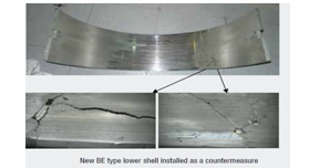
Blended Edge Design
The blended edge design consists of a smooth radius
that allows the main bearing shaft to incline without risking touching the
bearing edge or causing high oil film pressure near the edge. The blended edge
is described by two dimensions, its length and its depth. The actual values
depend on engine size and configuration.
credit to man b&w service letter
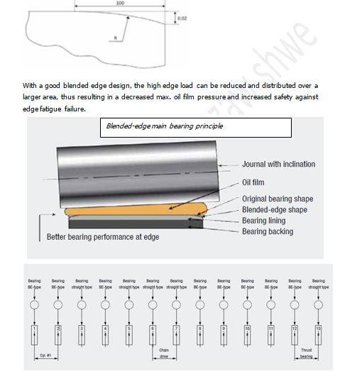
With a good blended edge design, the high edge load
can be reduced and distributed over a larger area, thus resulting in a
decreased max. oil film pressure and increased safety against edge fatigue
failure.
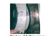
fatigue damage on the edge in bearing position No.
5, where a straight-edge main bearing was originally installed. The static
bearing imprint indicates that a concave geometry exists in this bearing
assembly, and a “straight-edge” check reveals that the main journal is concave.
In this case,
a BE lower bearing shell was installed, and the
issue was eliminated.

Lower
Oil Groove Removal(tangential
runout removal)
The oil groove feeds and distributes oil into the
bearing, but it also decreases the bearing area. On engines with high
horizontal load, the combination of blended edge and lower oil groove causes poor
fluid film conditions. The influence of the lower oil groove for the oil supply
is marginal and it is therefore considered better to remove the lower oil
groove to improve the horizontal bearing load capacity.

credit to man b&w manual
Spare Part Bearings
The trade off with blended edge bearings is its
decreased bearing load capacity when the inclinations are small and the bearing
force is very high. In such positions, “straight” cylindrical geometry bearings
are the better choice, and if blended edge bearings are specified elsewhere in
the same engine, it must be equipped with both plain and blended edge spare
parts. If an engine is delivered with a BE spare part bearing only, BE bearings
can be used in all
main
bearing positions.
This type of bearing has a steel
back with the required stiffness a) To ensure against distortion of the sliding
surface geometry, and b) To support the cast-on white metal in regions where
the shell lacks support, for example in the area of the upper shell mating
faces.The top clearances in this
bearing design are adjusted with shims, while the side clearances are a predetermined result of the summation of the
housing bore, shell wall thickness, journal tolerances, and the influence of
the staybolt tensioning force which deforms the bedplate around the bearing
assembly.
Thin shell bearings have a wall
thickness between 2% and 2.5% of the journal diameter.
The steel back does not have the
sufficient stiffness to support the cast-on white metal alone. The bearing must
therefore be supported rigidly over its full length. This type of bearing is
manufactured with a circumferential overlength (crush/nip) which, when the
shells are mounted and tightened up, will produce the required radial pressure
between the shell and the bearing housing. The maximum/minimum top clearance in
this shell is predetermined and results from a summation of the housing bore,
shell wall thickness, journal/pin diameter tolerances and, for main bearings,
the deformation of the bedplate from the staybolt tensioning force.
Cause of thin shell bearing
shifting
1-defective tag, 2-insufficient
nip clearance, 3-suddenly applied extreme load (pounding), 4-improper fitting,
5-correct size of bearing use, 6-due to overtighting bolts, 07-frictional force
from the back of shell and keep.
Top Clearance - Correct top clearance in main
bearings, crankpin bearings, and crosshead bearings is necessary to sustain the
required oil flow through the bearing, and hence stabilize the bearing
temperature at a level that will ensure the fatigue strength of the bearing
metal. In the main and crankpin
bearings, the clearance ensures the necessary space to accommodate the journal
orbit so as to avoid mechanical overload tendencies on the bearing sliding
surface (especially in the main bearing).The bearings are checked in general by
measuring the top clearances.In service, clearance measurements can be
regarded:1. as a check of the correct re-assembly of the bearing. For new thin
shell bearings and new/ overhauled thick shell bearings the clearances must lie
within the limits specified in the maintenance manual. 2. as an indicator to
determine the condition of the bearing at a periodic check ‘Checks without
opening-up’. In both cases, it is vital that the clearance values from the
previous check are available for comparison. Therefore, it is necessary to
enter clearances in the engine log book with the relevant date and engine
service hours.
Wear - Under normal service conditions,
bearing wear is negligible. Excessive wear is due to abrasive or corrosive
contamination of the system oil which will affect the roughness of the
journal/pin and increase the wear rate of the bearing.
The
reduction of shell thickness in the loaded area of the main, crankpin and
crosshead bearing in a given time interval represents the wear rate of the
bearing. Average bearing wear rate is 0.01 mm/10,000 hrs. As long as the wear
rate is in the region of this value, the bearing function can be regarded as
normal. For crosshead bearings, the wear
limit is confined to about 50% reduction of the oil wedge length.
Journals/Pins
Surface Roughness
Journal/pin surface roughness is
important for the bearing condition. Increased surface roughness can be caused
by: a) Abrasive damage due to contamination of the system oil.
b) Corrosive damage due to sea water
contamination of the system oil (acidic) or oxidation of the journals due to
condensate. c) Spark erosion (only in main bearings).
With increasing journal/pin
roughness, a level will be reached where the oil film thickness is no longer
sufficient, causing metal contact between journal/pin and the bearing sliding
surface. This will cause white metal to adhere to the journal/pin, giving the
surface a silvery white appearance. When
such a condition is observed, the journal/pin must be reconditioned by polishing,
and the roughness of the surface made acceptable. In extreme cases, the
journal/pin must be ground to an undersize.
Limits
to surface roughness
The surface roughness should
always be within the specified limits.1. For main and crankpin journals:
a) New journals 0.8 Ra
b) Roughness approaching 1.6 Ra
(journal to be reconditioned).
2. For crosshead pins:
a) New or repolished 0.05 Ra
b) Acceptable in service 0.05-0.1 Ra
c) Repolishing if over 0.1 Ra
Determination
of the pin/journal roughness
Measure the roughness with an
electronic roughness tester, or Evaluate the roughness with a Ruko tester, by
comparing the surface of the pin/journal with the specimens on the Ruko tester.
When performing this test, the pin surface and the Ruko tester must be
thoroughly clean and dry. Hold the tester close to the surface and compare the
surfaces. If necessary, use your finger nail to run over the pin/journal
surface and the Ruko specimens to compare and determine the roughness level.
BWM(bearing wear monitoring) Vs
OMD -A main
bearing damage was recently experienced on an MAN B&W S-MC-C main engine of
medium bore size. The damage was caused by a sudden ingress of foreign matter
into the bearing via the lubricating oil system, and it developed rapidly into
a bearing seizure.
Operation of the engine continued until the oil mist
detector (OMD) alarm set off and requested slow-down. At this stage, the
bearing damage had evolved into a situation where comprehensive repair of the
crankshaft and bearing housing (bedplate) was called for.

credit to man b&w service letter
Normally, main, crank pin and crosshead bearings
have very low wear rates. Wear rates up to 0.01 mm/10,000 hrs.
are considered acceptable, but lower values can be
expected under normal running conditions. Conversely, abnormal operating
conditions, e.g. pollution of the lubricating oil, scratches on journals or
spark erosion may give rise to significantly higher wear rates and ultimately
to bearing failure.
Continuous operation with an undetected bearing
failure may cause excessive heating, possibly damaging the shaft and bearing
housing. In particular, in case of a main bearing failure, the repair work may
become quite comprehensive.
To minimise the risk of bearing damage, and possible
consequential damage, inspection of the bearings is therefore recommended at
regular intervals.
External inspection of bearings
The following inspections are recommended to be
carried out at regular intervals.
Inside engine:
Bearing clearance measurements
Bearing edge check
Inspection of crankcase for
bearing metal
Crankshaft deflection measurement
Lubrication
system:
Inspection of oil filters
Oil analysis as described in the
“Operation” section of the instruction book.
Open-up inspection of
bearings
It is not recommended to open up bearings for
inspections unless this is found justified by the above-mentioned external
inspections or by other observations. The only exception is the open-up
inspection of crosshead bearings and crank pin bearings for every three piston
overhauls on engines not fitted with the monitoring systems(BWM)
Systems for monitoring and
protection of bearings
Recommended by MAN Diesel & Turbo (MDT) to
protect against bearing failure and consequential damage.
These can be categorised in two groups:
Bearing protection systems serving to detect particular
conditions of the bearing environment that may cause
bearing damage. MDT recommends Shaftline Earthing
Device Monitoring (SEDM) and Water In Oil Monitoring (WIOM).
Engine protection systems serving to detect a bearing damage
before it develops to cause damage to major parts of the engine. MDT recommends
Bearing Wear Monitoring (BWM) and Bearing Temperature Monitoring (BTM)
SEDM. Shaftline Earthing Device
Monitoring. A well-functioning shaft line earthing system is necessary to avoid
spark erosion in main bearings. Monitoring the electrical potential between
shaft and hull by a separate slip ring connected to
the alarm system ensures correct function of the system.
WIOM - Water In Oil Monitoring. In
several cases, water in the lubricating oil has resulted in poor bearing
performance. The lead-based overlayer used in crosshead bearings is sensitive
to water (corrosion), but also main bearings of both the White-Metal and
Tin-Aluminium types have been seen to suffer from water contamination.
BWM. Bearing Wear Monitoring is a
system that detects wear in any of the three crank train bearings, the main,
crank pin or crosshead bearings, by measuring the position of the crosshead
assembly in the bottom dead centre.

credit to man b&w service letter
The BWM system has threshold values for release of
alarm and engine slowdown, respectively.
BTM. Bearing Temperature Monitoring
systems have been available for MAN B&W engines for several years. A
variety in measuring principles and executions exists, but all systems serve to
release an alarm/slowdown when a bearing failure has developed to an extent
where heat is developed. (bearing housing design feature – bearing shells are
in place by interference fit, there is no relative movement of housing &
shell, effective heat transfer between shell & housing is essentail, cap
holding bolts are to be close pitched to prevent distortion, housing in robust
to prevent excessive strain on shell, housing is not too stiff to prevent
localized load concetration on bearing)

credit to diesel engine reference book
Types of bearing defects - 1.crack, 2. Fatigue failure of
white metal, 3.squeezing of white metal, so oil grooves are partially blocked,
4.wiping, 5. Faulty casting and faulty machining, 6.tin oxide corrosion, 7.acid
corrosion,8.thermal ratcheting, 9. Electrical potential, 10.fretting
Bearing damage cause –
Abrasion
This is still probably the most common form of
bearing damage, even though filtration standards are generally very high. Long
term operation with very fine debris in the oil, or short term operation with
coarser contaminant can result in abrasion and scoring of the surface of a
bearing roughening it to such an extent that overheating can occur due to the
surface roughness penetrating the thin oil film.
Fatigue
Typical fatigue damage of white metal is due to a
combination of load, high temperature, and the inconsistency of white metal
structure resulting from the direct lining of a large variable-cross-section
housing.
Corrosion
The different bearing alloys suffer corrosion under
different conditions. Tin-base white
metals, particularly in the slow-speed diesel engine, can form a hard,
dark (almost black) brittle surface
deposit when water is present in the lubricating
oil. Under these conditions, the bearing
becomes prone to overheating and seizure.
Alternatively, due to the brittle nature of the layer,
it can flake off the surface, leaving a generally
pitted appearance.
Copper-lead
lining, if
exposed to a lubricating oil which has thermally degraded to form organic acids
and peroxides, or become contaminated by sulphur containing fuel oils, blow-by
of products of combustion of such fuels, or cooling
water with antifreeze additives, is prone to corrosion of the lead phase of the
lining, be this either of the cast or sinter type.
Aluminium-based
linings are
completely resistant to engine oils, and to their high-temperature degradation
products. However, in direct contact with water, a film of aluminium oxide can
form in the bore, together with corrosion of the steel backing and possible
lifting of the lining material, although in an oil environment in an engine,
this is virtually impossible.
Service Letter SL05-460/NHN / November 2005 – corrosive wear
of crosshead bearing
Water in the lube oil system may lead to corrosive
wear of the overlayer and, eventually, mechanical damage to the crosshead
bearing, with high costs as a consequence. If the oil system becomes
contaminated with an amount of water exceeding our limit of 0.2% (0.5% for
short periods), acute corrosive wear of the crosshead bearing overlayer may
occur. The higher the water content, the faster the wear rate. A water content
higher than 1% could lead to critical damage within a few days in operation.
The overlayer in crosshead bearings consists of a thin, soft lead-tin-copper
galvanic alloy covering of the bearing lining metal. It is used in both
white-metal and AlSn40 (tin-aluminium) lined crosshead bearings. In AlSn40
bearings, the overlayer is always bonded to the bearing metal by a very thin interlayer
of Ni (nickel), or Ag (silver). There is no interlayer in white-metal based
bearings, but the risk of corrosion is still present. Wear of the overlayer
changes the geometry of the bearing surface and, thereby, the intended
"embedded arch" geometry. A change in the bearing geo-metry will
obstruct the oil film formation, which is critical for the correct functioning
of the crosshead bearing.
Furthermore, excessive wear of the overlayer in
AlSn40 bearings could, eventually, expose the interlayer to nickel-to-steel
contact with the cross-head pin, and result in scuffing action between the pin
and the bearing shell.
In
addition to damaging the compon-ents, there is, in extreme cases, a risk of a
crankcase explosion. AlSn40-based
crosshead bearings must urgently be replaced as soon as possible if an open-up
inspection shows more than 5% of the nickel layer exposed. If one bearing unit
has more than 5% of the Ni-layer exposed, it is very likely that all the other
units suffer from a similar extraordinary wear, and they should therefore be
replaced as well. To decide which bearings to inspect first, all top clearances
should be measured and compared with the shop test/sea trial records. If large
deviations are found, and/or if bearing "dust" is found in the
surrounding area in the frame box, those bearings should be the first to be
inspected.the lead content in the oil system can be used as a guideline: 0-4
ppm Normal, 5-10 ppm-Inspect filters and crankcase for bearing debris, and
prepare inspection of crosshead bearings when convenient, >10 ppm-Inspect
filters and crankcase for bearing debris, and prepare inspection of crosshead
bearings as soon as possible.

credit to man b&w service letter
Wiping
This type of damage can occur with any lining
material, and is caused by insufficient lubricating and cooling oil on the
bearing surface. This results in overheating and eventually melting of the
lowest melting-point phase of the lining alloy. Potential causes of
insufficient oil on the bearing
surface include inadequate generated oil film thickness,
insufficient clearance, housing distortion, restriction in oil supply system,
excessively worn bearings in other locations and
inadequate oil pump capacity.
Cavitation
Cavitation erosion damage to bearing surfaces is a
form of micro fatigue cracking, initiated by the collapse of vapour cavities.
Fretting
fretting of a bearing due to insufficient contact
pressure, local welding and tearing having
taken place between the bearing back and housing
bore, resulting in transfer of metal from one to the other. Where fretting of
the joint faces of the bearing occurs, this usually implies inadequate joint
face clamping force. Fretting of the housing joints can also be expected under
these conditions.Before fitting new bearings where fretting has occurred, all
trace of fretting build-up in the housing must be removed to avoid premature
catastrophic damage of the new bearing.
credit to man b&w service letter
This type of fretting was experience at L23/30H man
b& w engine --- (L23/30H man b& w engine (aux engine) main bearing
shell fretting - fretting/corrosion
between the main bearing shell and the main bearing cap on engines without main
bearing temperature sensors.The fretting/corrosion is caused by relative
movement between the bearing shell and cap during engine operation. The result
is that water and oil can migrate between the bearing shell and cap through the
sensor hole and cause the observed wear patterns on the bearing running
surface.( In order to stop further development of the fretting/corrosion, need to plug the hole in the main bearing cap and
fill the bore with a sealing compound; e.g. EN14AP.)
Design faults (above example of
L23/30H )
Major design faults will not generally be evident in
production engines because they would have been found out very quickly during
pre-production development testing
Incorrect assembly
The commonest causes of incorrect assembly are
associated with locating devices. Incorrect positioning will mean that oil feed
connections are misplaced and can block off the oil feed.
Incorrect location of a tang into its recess means
that the bearing back will not be in contact with the housing, and the
clearance between the bearing bore and the crankshaft can be lost, resulting in
local overheating of the bearing surface, and possibly seizure. Having located the
bearing correctly into its housing, care must be taken to ensure that the
housing bolts are correctly tensioned. Insufficient bolt load due to incorrect
tightening can result in the damage also excessive dynamic stressing of the
bolts and ultimate fatigue fracture. The bolts should also be tensioned in the
prescribed sequence given in the engine manual.
Environmental factors
Electrical discharge
- with
inadequate earthing, a discharge of current can occur through the oil
film between the journal surface and the bearing bore, resulting in
fine, cleanly defined
pitting of the bearing surface. Damage such
as this has been found to occur with an electrical potential in excess of only
50 mV.
Spark Erosion - Spark erosion is caused by a
voltage discharge between the main bearing and journal surface. The cause of
the potential is the development of a galvanic element between the ship’s hull,
sea water, and the propeller shaft/crankshaft. The oil film acts as a
dielectric. The puncture voltage in the bearing depends on the thickness of the
oil film. With increasing engine ratings, the specific load in the main bearing
is increased. This will reduce the oil film thickness, and enable the discharge
to take place at a lower voltage level. Since the hydrodynamic oil film
thickness varies through a rotation cycle, the discharge will take place at
roughly the same instant during each rotation cycle, i.e. when the film
thickness is at its minimum. The roughening will accordingly be concentrated in
certain areas on the journal surface. In the early stages, the roughened areas
can resemble pitting erosion - but later, as the roughness increases, the small
craters will scrape off and pick up white metal – hence the silvery white
appearance. Therefore, to ensure protection against spark erosion, the
potential level must be kept at maximum 80 mV, which is feasible today with a
high efficiency earthing device. If an earthing device is installed, its
effectiveness must be checked regularly. Spark erosion is only observed in main
bearings and main bearing journals. The
condition of the bearings must be evaluated to determine whether they can be
reconditioned or have to be discarded. Manufacturer is consulted.


credit to man b&w service letter
Journal wear ridge
Wear of the journal surface can occur due to
embedded hard contaminant in the bearing surface. Less wear occurs in the
region associated with grooves, gradually producing a ridge on
the journal surface,
which in turn causes wear of the bearing surface of partially grooved bearingsRidge wear will inevitably develop over time at the crank pin journal. The wear pattern is caused by abrasive impurities that remain in the lube oil. Efficient lube oil cleaning is therefore essential to keep the development of ridge wear as low as possible in trunk engines. Careful inspection and judgement of the crankpin journals must be carried out whenever a new crankpin bearing is installed.If ridge wear is observed, this must be rectified before new upper and lower bearing shells are installed.(need to ground down the crankpin to undersize to remove ridge wear)
Misalignment
Misalignment through whatever cause is typified by a
'D' pattern of wear, with the longest side on one end of the bearing, Causes
can be taper in the bearing housing or journal surface, debris trapped between
shell and housing, bruising of the steel backing of the bearing shell or
housing bore during assembly, taper through the bore of the bearing, or a
variation in alignment of a series of main bearing bores along the engine.
Geometric factors
Severe wear of localized regions of the bearing
surface are generally caused by specific geometric inaccuracies. Heavy wear in
the axial centre region is usually caused by a 'barrelled'
journal, whereas heavy wear at both ends of the
bearing results from an 'hour glass' profile.
Thermal
ratcheting –
caused by alternate cooling and heating of bearing, result in bearing
deformation, indication of high bearing temperature, most occurred at thrust
pad bearing surface.
Static fretting - The damage shown is caused by vibration of
a crankshaft within the bearing clearance. The term 'static' comes from the
fact that such damage only occurs when the engine is not running. The damage
can occur during transport of assembled engines to site. In marine
installations, generating sets mounted on flexible tank tops are prone to
similar damage. In such cases, the simplest palliative is to ensure that oil is
pumped through the bearing clearance every few hours while the engine is
inoperative(= must continuous run the pre-lube oil pump when stop
generator engine) ,
although in very severe instances it may also be necessary to redesign the
mountings (= installed on the resilience mounting).

Comments
Post a Comment