talk about steering gear system
1- steering gear system, telemotor, electro hydraulic, electric , ram type,
vane type Steering gear with 4 ram, floating lever - Hunting gear
arrangement with heleshaw pump(Constant
speed unidirectional rotary variable stroke positive displacement)
You can read about common problems of steering gear system at the following link
(Select the whole link address with right clip and open link in new window)
You can read about common problems of steering gear system at the following link
(Select the whole link address with right clip and open link in new window)

Safety devices for steering gear system
1-hunting gear, 2-buffer spring, 3-angle
adjusting stop, 4-double shock valve, 5-relief valve, 6-tank level alarm( oil
leak alarm), 7-overload alarm, 8-electrical failure, 9-hydraulic lock, 10-
filter clog ,11- phase failure alarm, 8-servo loop alarm at electro hydraulic
system( in case of different between rudder angle command & actual rudder
angle)
Steering clear (four ram types)
The
tiller is fixed to the rudder stock and the hydraulic rams operate it by means of
swivel blocks carried in forks of the ram.
The swivel blocks are designed to
convert linear movement of the rams to the rotary movement to the tiller
arms and the rudder stock.
Each pair of rams is bolted together,
the joint end being bored vertically and bushed to form top and bottom bearings for the reunion
arms on the swivel block.
Hydraulic pressure is supplied by the
motor driven, constant speed, variable stroke delivery pumps. Amount and direction of oil
flow is controlled by the movement of the pump control rod, which is linked
to the floating lever.
Hand operated by pass valve combined with spring loaded double shock valves are fitted across the hydraulic circuits.
Shocks
vales are set to lift at a pressure of 100 bar and are intend to allow the rudder to give way when it is subjected to a severe shock from a heavy
sea or other causes.
The
linkage through the floating lever of telemotor, pump control rod and rudder
stock forms the hunting gear.

The pump delivers oil, only when the
steering wheel is moved. The hunting gear returns the pump control rod to mid position as soon
as the rudder received the position relative to the wheel and remains there the wheel
move again.
The telemotor moves the end of the
floating rod A to A1 and the pump control rod moves B to B1. Pumping of the hydraulic oil causes
movement of the tiller arm, through rams and the end of rod C moves to C1.
These movements cause the pump control to pull back to the neutral position B.
If the rudder is rotate by the heavy
sea through lifting of the shock valves, the hunting gear is moves by the
tiller. This put the pump to work and the rudder will be restored to
its previous position.
Follow up & non follow up - The control system described up to this point are all
associated with "Follow up" or "Hunting Gear" systems,
wherein the amount of rudder angle depends upon the amount of hand-wheel
movement. In "Non-follow up" system, the steering gear will move as long as the
control is held in an actuating position, and will only
stop when it is moved back to an "Off" position or until the steering
gear has reached the hard-over position.
Thus, the amount of rudder movement depends upon how long the control is held
over and this system is therefore sometimes called "time dependent
steering". The control on the bridge is by means of a lever, which is spring loaded to a central
"off" position and when held to one side, will give rudder movement towards port and to the other side towards
starboard. The lever operates a switch, which energizes one of two
solenoids, depending upon the direction of movement required.
These solenoids operate a pilot valve, which causes the main control
valve to move, so as to divert oil pressure from a continuously running fixed delivery pump to the steering
gear in order to give the desired direction of rudder movement. When the switch is released, springs to the central position, the control valve moves to a position, where it bypasses the pump
delivery, and the steering gear stops. At the same time, the control valve
seals off the pipes to the steering gear stops. At the same time, the control
valve seals off the pipes to the main cylinders so as to hold the rudder. Since the
rudder moves as long as the control lever is held over by the helmsman, and stops moving as soon
as the lever is released to spring to the "off" position, the
helmsman acts as the hunting gear, stopping rudder movement as soon as it has
reached the desired angle as signaled by the rudder indicator. Therefore the
rudder indicator becomes an essential link in the steering gear system &
together with helmsman completes the control loop.

credit to marine electrical technology by Elstan A Fernandez
How to operate if one ram and cylinder fail
How to operate if one ram and cylinder fail
~
(1)
For cylinders 1 and 2 operational, with valves B, C and F open, A, D and E
closed (2) For Cylinder 3 and 4 are operational, with valves A, D and E
open B, C and F Closed I.e. isolating 2 rams (not diagonally)
~
Use
only one pump at any time,
~
Ship’s
speed should be reduced to 70% of normal, if large rudder angles are expected
e.g. in heavy weather or enclosed waters etc.
~
Preferably
watches should be kept in steering compartment
~
Locking
arrangement should be ensured on all valves, which have been altered
~
Informed
Bridge on limitations of steering system.
Fail safe steering gear system
for UMS
~
There are basically two pairs of rams, which can be operated by two
independent Steering motors. In case
of single failure, the leaking circuit has to be detected and isolated, in
order to restore steering.
~
In case of oil leakage in either of the steering circuits (Single
Failure), there will first be an indication (low level alarm), then the isolating valve will operate,
and if the level falls further (Low-Low level), the second motor will start with its isolating valve
already operated, and the first motor will stop. One Steering motor can isolate only one pair of
rams, hence if the fault is in the other pair, the second
Steering motor needs to be started. This is an essential requirement in Tankers
above 10,000 GRT

The telemotor system consists of the transmitter (in
wheelhouse) and the receiver (in steering gear room), which are connected with
two solid drawn copper pipes. The transmitter consists of movable single acting bronze
rams in two cylinders. The upper ends of the rams are extended to form racks.
They are engaged with the steering wheel through gearing.
The receiver consists of stationary two
fixed rams and one movable cylinder along the rams. Each outer end of ram short
pipe is lead to circuit valve and it is connected
to bottom of transmitter cylinder.
Any fluid displaced in the transmitter
cylinder by the ram is forced through pipe and circuit valve to the
receiver cylinder.
Movement of cylinder must against the
spring force, which brings back to mid position when wheel is put back into mid position.
One end of the receiver cylinder is
connected to the floating lever and the movement is transmitted through the cross head. A replenishing
tank is above the highest part of cylinder to prevent air into system.
Air in the system
Air being compressible gives incorrect
balance between units, time lags and abnormal
operation, which can be dangerous.
Air in the system is indicated by
defective steering, excessive movement of steering
wheel before telemotor move.
No initial pressure and wheel slack on
turning, jerky operation and perhaps jumping
at the pressure gauges.
Rectify
Air can be purged out from air vents
valves. If there is considerable air inside the system, the system oils should
be totally emptied and recharged completely.
Emergency steering gear
In the case of telemotor failure, by
switching the change over pin, emergency steering
can be carried out by isolating the receiver cylinder.
And direct controlling the connecting
rod of the main steering power unit's pump lever. The emergency rudder angle
indicator and communication system to bridge being provided at
the emergency station.
Washing
Out and Charging Procedure
The charging and the replenishing
tanks must be carefully washed out before charging the system. In order to
clear the pipes of all dirt and grit, the followings must be carried out.
Disconnect pipes B and C at the
transmitter end and connect these two ends to a wash out piece. Then disconnect
pipes A and C at receiver end. Fill the charging tank with fresh oil and pump
until a quantity of oil has passes through pipe A. Connect pipe A to receiver.
Open all charging and circuit valves. Insert end of pipe C into a bucket and
continue pumping.
To ensure the pump does not draw air
the charging tank should be recharged at intervals. Pumping must be continued
until the oil discharged through pipe C is free from dirts.
The pipe now being cleaned, connect
pipe C to the receiver. Disconnect wash out piece and pipes B and C connect
back to the transmitter.
Put the steering wheel into the mid position and open safety by-pass
valve by means of lever. These valves can be opened when the wheel is in mid
position and the wheel will be locked in this position while these valves are
opening.
Open
valve J and pump the charging pump until oil rise in the replenishing tank to
the working level. Close valve J and release air at the air cocks on the
transmitter. Then release air at air cocks on the receiver. Continue pumping
until for each stroke of the pump a rush of oil comes from the return pipe D.
Close the charging valves, open valve J and release the safety by-pass lever.
Tests required before departure
o
Steering
gear should be checked at least one hour prior to departure.
o
Duty
Officer and senior Duty Engineer carryout test together
o
Telemotor
transmitter oil level to be checked.
o
Oil
level of the actuating system tank should be checked and replenished if
necessary.
o
Rudder
carrier bearing and bottom sea gland checked and greased
o
All
links on steering gear checked to be in order
o
First
one pump is started from the bridge and the Wheel is turned from port to
starboard to check telemotor response
o
Next
with both the officers in steering flat, the wheel is turned from hard-a-port
to hard-a-starboard and running condition checked
o
Checked
if the Bridge helm angle indicator and local mechanical indicator correspond
correctly to each other for all position
o
The
first pump is shut off and the second pump started and check likewise
o
Then
both pumps started in parallel and check likewise again
o
Check
load carrying and running of the gear.
Before Arrival Port
o One
hour before picking-up Pilot, ME speed reduced and engine manoeuvring, astern running,
and all steering gear actuation checked
o Both
pumps are started and movements on either side checked
o Bridge
angle indicator and local indicator checked for correct matching response on
either side.
Hydraulic pump -Hele-Shaw Pump, Swashplate
Pump, Vane Pump
Piston Pump. On an inline piston pump, the
drive shaft and the cylinder block are on the same centerline

CREDIT TO BASIC OF HYDRAULIC
Reciprocation of the pistons
occurs when the pistons run against a swash plate as the cylinder block
rotates. The drive shaft turns the cylinder block, which carries the pistons
around the shaft. The piston shoes slide against the swash plate and are held against
it by the shoeretainer plate. The angle of the swash plate causes the cylinders
to reciprocate in their bores. When a piston begins to retract, the opening on
the end of the bore slides over the inlet slot in the valve plate and oil is
drawn into the bore through less than onehalf a revolution of the cylinder
block. A solid area is created in the valve plate, and the piston retracts. As
the piston begins to extend the opening, the cylinder barrel moves over the
inlet port and oil is forced through the outlet port.
a- The major components of a
piston pump consist of a housing, a bearingsupported drive shaft, a rotating
group, a shaft seal, and a valve plate. The valve plate contains the inlet and
outlet ports and functions as the back cover. The rotating group includes a
cylinder block, which is splined to the drive shaft; a splined spherical
washer; a cylinderblock spring; nine pistons with shoes; a swash plate; and a
shoeretainer plate. When this group is assembled, the cylinderblock spring
forces the cylinder block against the valve plate and the spherical washer
against the shoe retainer plate. The nine piston shoes are held
positively against the swash plate, ensuring that the pistons
reciprocate as the cylinder turns. In fixeddisplacement pumps, the swash
plate is stationary.
b. Displacement (outflow) from
the piston pump depends on the number of pistons, their bore, and their stroke.
The swash plate's angle determines the stroke; therefore, the stroke can be
changed by altering the angle
CREDIT TO BASIC OF HYDRAULIC
Constant speed unidirectional rotary variable stroke
positive displacement
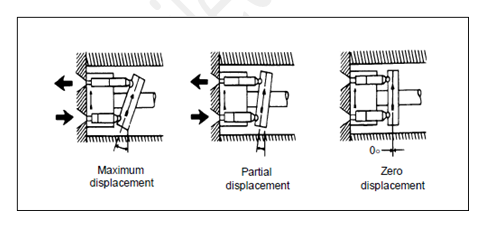
The pump consists of
central valve arrangement by ports for the supply and delivery of oils. The
pistons are fitted in the radial cylinders and fasten to slippers by a gudgeon
pin.
The slipper fit into
a track in the circular floating ring. When the floating ring is concentric
with the valve the pistons have no relative reciprocating movement in the
cylinders.
As
a result no oil is deliver and although the pump rotating. If the floating ring
is pulled to right, the relative reciprocating motion of pistons in the
cylinders occur.
The lower piston will
move inwards and discharge fluid out through the lower port. As it continues
passed the horizontal position, the piston will move outwards and draw fluid in
from the upper port.
Once
past the horizontal position on the opposite side, it begins to discharge the
fluid. If the circular floating ring is pushed to left side, then the suction
and discharge ports will be reversed.
To prevent reversal of pump

Two nos. of positive
displacement pumps are fitted in the system and only one is operating, reverse
operation of other is prevented by non- reverse locking gear.
It consists of a
number of steel pawls are mounted on the coupling and stationary steel ratchet
is fixed to the motor supporting structure.
At rest the pawls
engage into the ratchet, the other pump running the sense of rotation in
reverse order it will not be able to turn.
When the pump starts
the reverse sense of rotation pawls fly outwards due to centrifugal force and
can rotate freely.
rotary vane
type steering gear


It consists of a rotor with vanes
which can move in stator casing. A rotor is securely keyed to the tapered rudder stock. The stator is
solidly attached to the ship's structure. The sealing strips are fitted on the moving face of the
rotary and fixed vane
Chambers are formed between the
rotating vanes and fixed vane of the stator casing.
These cambers are alternately connected to the suction and delivery from the hydraulic pump.
Its supply hydraulic fluid to all
chambers on the left and drawing fluid from all chamber on
the right the rudder can be turned anti clockwise and clockwise movement
the circuit is reversed.

Hydraulic
pumps are controlled by telemotor unit through floating lever type hunting gear
arrangement to ensure the rudder can stop when steering gear wheel
standstill.
A relief valve is fitted in the system
to prevent over pressure and allow for shock loading of rudder. The whole
weight of gear is taken up by rudder carrier bearing. Two anchor bolts held
in fixed anchor brackets with rubber shock absorbing sleeves prevent the rotation
movement.
Vanes are made of spheroid graphite
cast iron; the rotor and stator are cast steel. Synthetic rubber backs steel sealing strips.
Advantages
over Ram Type
(1) Smaller space required
(2) Low installation cost
(3) Low in weight
(4) Smaller power required, for the
same load, because it can transmit pure torque to the rudder stock.
Disadvantages
(1) Synthetic rubber backed steel
sealing strips at vane tips are not strong enough for large ship gears.
(2) Can be used for rudder stock
ratings of about 1700 KNm and less (torque generated by two ram is 120 to 650
KNm and for four ram 250 to 10,000 KNm)
ROTARY VANE
VERSUS RAM TYPE
RAM TYPE
|
ROTARY VANE
TYPE
|
|
1
|
Torque about 1,000 KNm in 4 ram
type and 650 KNm in two ram type
|
More adaptable to increase of
Torque produces
about 3,000 KNm
|
2
|
Withstand Maximum pressure about
170 Bar
|
Limited pressure about 90 Bar
|
3
|
Having efficient sealing
|
Sealing difficulties
|
4
|
More Robust
|
More careful attention required
for Rudder support and shock loading owing to its very close and direct
connection between Rudder and Actuator.
|
5
|
Suitable for all sizes and types
of ships
|
Suitable for small and medium
sizes excluding larger vessels.
|
6
|
Saving in cost, weight, space and
maintenance
|
|
7
|
Limited rudder angles up to 35' each
side only
|
Wider working Rudder angles,
giving 70°
to 80°.
|
How to
lubricate upper and lower radial bearing and a thrust bearing of rotary vane
steering gear
PORSGRUNN ROTARY VANE STEERING
GEAR.
Function
rudder fall off.
The rotary vane steering gear is
working like a type of hydraulic motor with limited movement.
In the housing we have two
stoppers limiting the movement, where normal movement
is 2 x 37 or 2 x 65
We have an upper and lower radial
bearing and a thrust bearing, all lubricated through the system oil. Oil for
lubricating of the bearings will during running have a flow from pressure side
to low pressure side in the actuator. This condition will result in an internal
liquid by pass.
With steering control in
NFU-mode, i.e. emergency steering, and no order given the rudder will fall off
to the side with lowest pressure.
With the steering control in
F.U.-mode the falling off will be taken care of by the autopilot system. The
dead band of the follow up system should normally be 0.5 to 1.0 degree.
The mech. limit switches should
be adjusted to 1 degree below max. possible rudder
angle. The electronic limitation
should be adjusted to 1 degree below adjustment of the mech. limit switches and
allow a dead band like 0,5 degree.
The time registration for rudder
falling off depends on actual rudder force, rudder angle, speed of vessel, and
will always be different for each steering gear actuator and also type of
vessel.
Due to the design of our sealing
system our experience is that the rudder falling off time will be reduced after
a time is service, however an internal liquid by pass will always be present in
order to lubricate and wash the bearings. In that way the lubrication oil for
the bearings is changed continuos.
RUDDER ACTUATOR MAIN COMPONENTS:
Type of rotor : Cast in one piece
w/two vanes
Material - rotor : Nodular cast
iron:
Material – housing/cover/stoppers
: Nodular cast iron:
Material - linings and rudder
bearing : JM1-15 Johnson Metall
Cu 85%, Sn 4-6%, Pb 4-6%, Zn 4-6%
Material sealings : Unpressurized
sealing rudderstock / steering gear:Box sealing
Sealing rotor / cover:Spring
loaded cast iron sealing ring.
Sealing in vanes and stoppers:
founded iron GG-25 w/tensioned springs.
DESCRIPTION OF STEERING GEAR
FUNCTION AND DESIGN.
STANDARD
TYPE
The Porsgrunn rotary vane
steering gear actuator is provided with two vanes.
It is a keyless conical
connection between rudder stock and rotor, and the oil injection method is used for the fit. Rudder stock
nut with pull up piston on top of the stock.
The actuator is provided with
internal mechanical stoppers to limit the max. rudder angle.
Built into the lower section is a
fixed bronze radial bearing and a floating rudder carrier of the same material.
The upper part has a fixed radial
bronze bearing. The bearings are lubricated by the steering gear system oil.
The loads/forces from
rudder/rudder stock are taken by the upper and lower radial bearings and the rudder carrier. The torque is
transferred to the hull via staybolts (fitbolts) in the stoppers.
Valve-block with pilotvalve (type
On / Off) and shut off valves (fast acting) are mounted direct on the housing or on the cover.
Relief valves are incorporated in the control valves for the protection of the pumps.
There are at least two off power
units.
One common “leak” tank, open to
air, is mounted at the top of the actuator,with pipelines to the Pump tanks.
Mechanical rudder indicator,
rudder angle transmitter, feed backs and rudder angle limit
switches are mounted on the
expansion tank.
The “leak” tank is permanently
connected to a storage oil tank.
One or two relief valves are
mounted direct on the housing or on the cover in order to protect the actuator.
One common level switch is
mounted on the “leak” tank and one in each of the pump tanks.
Steering gear room: Electric
starters with instruments, start-stop switch. Device for Remote/Local steering
control. Local steering control of NFU mode or directly on the magnetic valves.
E.C.R.:Panels with run
indications and alarm indications for el. failure, hydraulic lock and low oil levels.
W.H.: Panels with
start-stop-standby functions.
Run indications, steering control
ready, remote and local indication, alarm indications for el.failure, hydraulic
lock, filter clogged, and oil low levels.
2.
FUNCTION
Start-Stop/Stand by:Start/stop
may be operated from two places:
Wheel house - Steering gear room.
The start/stop - operation is
normally a manual operation.
"Start/Stop" by means
of "Pulse switch" and "Step relay". The "Step
relay" can also be manually operated, (inside starters).The two hydraulic
power units may be operated separate or together.
Auto-start based on following and
stand by mode.
a. At
electrical failure.
b. At
oil leakage.
c. At
hydraulic lock
Only alarm as follows.
Phase alarm. Pump stopped.
Low level in “leak” tank, (run or
not run).
Filter clogged.
Steering control: If steering
control is transferred to "Local". This mode will either not allow
"stand by" of the next pump. The indication lamp "Local" on
bridge will light.
"Stand by" in one power
unit will always be set automatically when the other one is started manually.
"Stand by" in one power
unit will always be set automatically when one power unit is stopped in a
normal way.
"Stand by" can also be
set and reset manually by the push button "Stand by".
Power unit in operation can not
be in "Stand by".
Power unit out of order due to a
failure can not be in "Stand by".
A.
ELECTRICAL FUNCTION FAILURE.
The following will be monitored
for electrical failure:
1. Overloaded alarm
2. Phase alarm
3. Steering control alarm
4. Power
5- Phase alarm and Power have same nature in
the system and therefore have common alarm.
By all alarms we have flash-light
and pulsating sound signal until acknowledge.
B. OIL
LEAKAGE
Common oil level switch in “leak”
tank. This tank is common for both power units.
One level switch in each pump
tank. Alarm on low level.
B1.
FILTER CLOGGED
Each pump tank have built in a
return filter with a pressure drop measuring indicator. The task
of the indicator is to monitor
the filter condition and will be activated before the filter is in by
pass.
C.
HYDRAULIC LOCK
You can watch at the following link the explanation about hydraulic lock
https://www.youtube.com/watch?v=uCnpCBcG7vc
You can watch at the following link the explanation about hydraulic lock
https://www.youtube.com/watch?v=uCnpCBcG7vc
The function is monitoring the
valve block function, based on steering control signal from
wheel house and the response from
the main directional spool.
Alarms:
All common alarms are based on
N.C. contacts. Alarm will occur when we have a break in the circuit.
When an alarm occur, the specific
alarm lamp start flashing and the buzzer is activated, until
acknowledge. Then we have a fixed
light and no sound as long as the alarm condition remain.
If a new alarm occur, the
procedure starts again.
If the power unit has been
stopped before acknowledge, the flashing alarm and sound will be there until acknowledge. If the
condition for the alarm disappear before acknowledge, the flashing alarm and
sound will be there until acknowledge, but there will be no fixed light after
acknowledge. All alarms are delayed for 2 till 5 sec., filter clogged is
delayed 5 min. at start of pump, thereafter 10 sec. All alarms activate one
common output. Pot-free.
The system is based on
"Single failure" criteria.
Autostart:One power unit has to be in
operation. The other power unit to be in "Stand by". If not in
"Stan-by" we will only have alarm.
|
|


credit to PORSGRUNN ROTARY VANE STEERING GEAR MANUAL
Chambers
are formed between the sealing bars on rotor and the stopper bars in stator
casing. These chambers will vary in size as the rotor move and can be
pressurized since spring back sealing bar.
Chambers
are alternatively connected to the suction and delivery pipe from hydraulic
pumps so that low and high pressure compartments are created which produced the
rudder actuating torque.
Steering gear oil
1-low
pour point(-50’C), 2-low viscosity (redwood 30 secs at 60’C), 3-High flash
point(150’C) closed,4-non corrosive, 5-non sludge forming 6-non freezing,
7-good lubricating properties with high V.I(110)


credit to PORSGRUNN ROTARY VANE STEERING GEAR MANUAL
Regulation
29 - Steering gear
1.
Unless expressly provided otherwise, every ship shall be provided with a main
steering gear and an auxiliary steering gear to the satisfaction of the
Administration. The main steering gear and the auxiliary steering gear shall be
so arranged that the failure of one of them will not render the other one
inoperative.
2.1.
All the steering gear components and the rudder stock shall be of sound and
reliable construction to the satisfaction of the Administration. Special
consideration shall be given to the suitability of any essential component
which is not duplicated. Any such essential component shall, where appropriate,
utilize antifriction bearings such as ball-bearings, roller-bearings or
sleeve-bearings which shall be permanently lubricated or provided with
lubrication fittings.
2.2.
The design pressure for calculations to determine the scantlings of piping and
other steering gear components subjected to internal hydraulic pressure shall
be at least 1.25 times the maximum working pressure to be expected under the
operational conditions specified in paragraph 3.2, taking into account any
pressure which may exist in the low-pressure side of the system. At the
discretion of the Administration, fatigue criteria shall be applied for the
design of piping and components, taking into account pulsating pressures due to
dynamic loads.
2.3.
Relief valves shall be fitted to any part of the hydraulic system which can be
isolated and in which pressure can be generated from the power source or from
external forces. The setting of the relief valves shall not exceed the design
pressure. The valves shall be of adequate size and so arranged as to avoid an
undue rise in pressure above the design pressure.
3.
The main steering gear and rudder stock shall be:
.1. of
adequate strength and capable of steering the ship at maximum ahead service
speed which shall be demonstrated;
.2. capable
of putting the rudder over from 35° on one side to 35° on the other side with
the ship at its deepest seagoing draught and running ahead at maximum ahead
service speed and, under the same conditions, from 35° on either side to 30° on
the other side in not more than 28 s; Where it is impractical to demonstrate
compliance with this requirement during sea trails with the ship at its deepest
seagoing draught and running ahead at the speed corresponding to the number of
max continuous revolution of the main engine and max design pitch, ships
regardless of date of construction may demonstrate compliance with this
requirement by one of the following methods:
1-during sea trails the ship is at
even keel and the rudder fully submerged whilst running ahead at the speed
corresponding to the number of max continuous rev of the main engine and max
design pitch: or
2-where full rudder immersion during
sea trails cannot be achieved, an appropriate ahead speed shall be calculated
using the submerged rudder blade area in the proposed sea trail loading
condition. The calculated ahead speed shall result in a force and torque
applied to the main steering gear which is at least as great as if it was being
tested with the ship at its deepest seagoing draught and running ahead at the
speed corresponding to the number of maax continuous rev of the main engine and
max design pitch: or
3-the rudder force and torque at the
sea trial loading condition have been reliably predicted and extrapolated to
the full load condition. The speed of the ship shall correspond to the number
of max continuous rev of the main engine and max design pitch of the propeller.
.3. operated
by power where necessary to meet the requirements of paragraph 3.2 and in any
case when the Administration requires a rudder stock of over 120 mm diameter in
way of the tiller, excluding strengthening for navigation in ice; and
.4. so
designed that they will not be damaged at maximum astern speed; however, this
design requirement need not be proved by trials at maximum astern speed and
maximum rudder angle.
4.
The auxiliary steering gear shall be:
.1. of
adequate strength and capable of steering the ship at navigable speed and of
being brought speedily into action in an emergency;
.2. capable
of putting the rudder over from 15° on one side to 15° on the other side in not
more than 60 s with the ship at its deepest seagoing draught and running ahead
at one half of the maximum ahead service speed or 7 knots, whichever is the
greater; and
.3. operated
by power where necessary to meet the requirements of paragraph 4.2 and in any
case when the Administration requires a rudder stock of over 230 mm diameter in
way of the tiller, excluding strengthening for navigation in ice.
5.
Main and auxiliary steering gear power units shall be:
.1. arranged
to restart automatically when power is restored after a power failure; and
.2. capable
of being brought into operation from a position on the navigation bridge. In
the event of a power failure to any one of the steering gear power units, an
audible and visual alarm shall be given on the navigation bridge.
6.1.
Where the main steering gear comprises two or more identical power units, an
auxiliary steering gear need not be fitted, provided that:
.1. in a
passenger ship, the main steering gear is capable of operating the rudder as
required by paragraph 3.2 while any one of the power units is out of operation;
.2. in a
cargo ship, the main steering gear is capable of operating the rudder as
required by paragraph 3.2 while operating with all power units;
.3. the main
steering gear is so arranged that after a single failure in its piping system
or in one of the power units the defect can be isolated so that steering
capability can be maintained or speedily regained.
6.2.
The Administration may, until 1 September 1986, accept the fitting of a
steering gear which has a proven record of reliability but does not comply with
the requirements of paragraph 6.1.3 for a hydraulic system.
6.3.
Steering gears, other than of the hydraulic type, shall achieve standards equivalent
to the requirements of this paragraph to the satisfaction of the
Administration.
7.
Steering gear control shall be provided:
.1. for the
main steering gear, both on the navigation bridge and in the steering gear
compartment;
.2. where
the main steering gear is arranged in accordance with paragraph 6, by two
independent control systems, both operable from the navigation bridge. This
does not require duplication of the steering wheel or steering lever. Where the
control system consists of a hydraulic telemotor, a second independent system
need not be fitted, except in a tanker, chemical tanker or gas carrier of
10,000 tons gross tonnage and upwards;
.3. for the
auxiliary steering gear, in the steering gear compartment and, if
power-operated, it shall also be operable from the navigation bridge and shall
be independent of the control system for the main steering gear.
8.
Any main and auxiliary steering gear control system operable from the
navigation bridge shall comply with the following:
.1. if
electric, it shall be served by its own separate circuit supplied from a
steering gear power circuit from a point within the steering gear compartment,
or directly from switchboard busbars supplying that steering gear power circuit
at a point on the switchboard adjacent to the supply to the steering gear power
circuit;
.2. means
shall be provided in the steering gear compartment for disconnecting any
control system operable from the navigation bridge from the steering gear it
serves;
.3. the
system shall be capable of being brought into operation from a position on the
navigation bridge;
.4. in the
event of a failure of electrical power supply to the control system, an audible
and visual alarm shall be given on the navigation bridge; and
.5. short
circuit protection only shall be provided for steering gear control supply
circuits.
9.
The electrical power circuits and the steering gear control systems with their
associated components, cables and pipes required by this regulation and by regulation 30 shall be separated as far as is
practicable throughout their length.
10.
A means of communication shall be provided between the navigation bridge and
the steering gear compartment.
11.
The angular position of the rudder shall:
.1. if the
main steering gear is power-operated, be indicated on the navigation bridge.
The rudder angle indication shall be independent of the steering gear control
system;
.2. be
recognizable in the steering gear compartment.
12.
Hydraulic power-operated steering gear shall be provided with the following:
.1.
arrangements to maintain the cleanliness of the hydraulic fluid taking into
consideration the type and design of the hydraulic system;
.2. a
low-level alarm for each hydraulic fluid reservoir to give the earliest
practicable indication of hydraulic fluid leakage. Audible and visual alarms
shall be given on the navigation bridge and in the machinery space where they
can be readily observed; and
.3. a fixed
storage tank having sufficient capacity to recharge at least one power
actuating system including the reservoir, where the main steering gear is
required to be power-operated. The storage tank shall be permanently connected
by piping in such a manner that the hydraulic systems can be readily recharged
from a position within the steering gear compartment and shall be provided with
a contents gauge.
13.
The steering gear compartments shall be:
.1. readily
accessible and, as far as practicable, separated from machinery spaces; and
.2. provided
with suitable arrangements to ensure working access to steering gear machinery
and controls. These arrangements shall include handrails and gratings or other
nonslip surfaces to ensure suitable working conditions in the event of
hydraulic fluid leakage.
14.
Where the rudder stock is required to be over 230 mm diameter in way of the
tiller, excluding strengthening for navigation in ice, an alternative power supply,
sufficient at least to supply the steering gear power unit which complies with
the requirements of paragraph 4.2 and also its associated control system and
the rudder angle indicator, shall be provided automatically, within 45 s,
either from the emergency source of electrical power or from an independent
source of power located in the steering gear compartment. This independent
source of power shall be used only for this purpose. In every ship of 10,000
gross tonnage and upwards, the alternative power supply shall have a capacity
for at least 30 min of continuous operation and in any other ship for at least
10 min.
15.
In every tanker, chemical tanker or gas carrier of 10,000 gross tonnage and
upwards and in every other ship of 70,000 gross tonnage and upwards, the main
steering gear shall comprise two or more identical power units complying with
the provisions of paragraph 6.
16.
Every tanker, chemical tanker or gas carrier of 10,000 gross tonnage and
upwards shall, subject to paragraph 17, comply with the following:
.1. the main
steering gear shall be so arranged that in the event of loss of steering
capability due to a single failure in any part of one of the power actuating
systems of the main steering gear, excluding the tiller, quadrant or components
serving the same purpose, or seizure of the rudder actuators, steering
capability shall be regained in not more than 45 s after the loss of one power
actuating system;
.2. the main
steering gear shall comprise either:
.2.1.
two independent and separate power actuating systems, each capable of meeting
the requirements of paragraph 3.2; or
.2.2.
at least two identical power actuating systems which, acting simultaneously in
normal operation, shall be capable of meeting the requirements of paragraph 3.2.
Where necessary to comply with this requirement, interconnection of hydraulic
power actuating systems shall be provided. Loss of hydraulic fluid from one
system shall be capable of being detected and the defective system
automatically isolated so that the other actuating system or systems shall
remain fully operational;
.3. steering
gears other than of the hydraulic type shall achieve equivalent standards.
17.
For tankers, chemical tankers or gas carriers of 10,000 gross tonnage and
upwards, but of less than 100,000 tonnes deadweight, solutions other than those
set out in paragraph 16, which need not apply the single failure criterion to
the rudder actuator or actuators, may be permitted provided that an equivalent
safety standard is achieved and that:
.1.
following loss of steering capability due to a single failure of any part of
the piping system or in one of the power units, steering capability shall be
regained within 45 s; and
.2. two
independent steering gear control systems shall be provided each of which can
be operated from the navigation bridge. This does not require duplication of
the steering wheel or steering lever;
.3. if the
steering gear control system in operation fails, the second system shall be
capable of being brought into immediate operation from the navigation bridge;
and
.4. each
steering gear control system, if electric, shall be served by its own
separate circuit supplied from the steering gear power circuit or directly from
switchboard busbars supplying that steering gear power circuit at a point
on the switchboard adjacent to the supply to the steering gear power circuit.
20.
In addition to the requirements of paragraph 19, in every tanker, chemical
tanker or gas carrier of 40,000 gross tonnage and upwards, constructed before 1
September 1984, the steering gear shall, not later than 1 September 1988, be so
arranged that, in the event of a single failure of the piping or of one of the
power units, steering capability can be maintained or the rudder movement can
be limited so that steering capability can be speedily regained. This shall be
achieved by:
.1. an
independent means of restraining the rudder; or
.2.
fast-acting valves which may be manually operated to isolate the actuator or
actuators from the external hydraulic piping together with a means of directly
refilling the actuators by a fixed independent power-operated pump and piping
system; or
.3. an
arrangement such that, where hydraulic power systems are interconnected, loss
of hydraulic fluid from one system shall be detected and the defective system
isolated either automatically or from the navigation bridge so that the other
system remains fully operational.


credit to marine electrical technology by Elstan A Fernandez
Electro-hydraulic Control--Turning a wheel causes change a
value at potmeter that attached to steering wheel. Pot meter fitted at steering
wheel give signal to B channel (terminal 1 & 11) and Pot meter fitted at
rudder stock give rudder angle feedback signal to A channel (terminal 1 &
2) of 2286A. 2286
A CPU will detect and calculate
the error between B channel (terminal 1 & 11) & A channel ( terminal 1
& 2). After calculated error, CPU will send correcting signal by activating
relay 1 or relay 2 correspondingly. Activating action of relay 1 or relay 2
will drive the DCV of hydraulic pump to receive port or stb movement of ram. local (manual) control of the steering gear was
achieved by electrically operate local control switch at steering gear room.
Two-ram
Electrically-controlled, Hydraulically-operated Steering System
Adventage of electrically control
hydraulically operate steering gear - Compatibility with complex control
systems, Less running hours for pumps, Increased reliability, Easy and quick changeover to a standby
hydraulic system, Local control from the
unit itself in case of an emergency.
Electro-hydraulic Steering Gear is of the
"Rapson Slide Type" construction and consists mainly of tiller, ram
and ram pin, hydraulic cylinder, axial piston pump, valves and pipings.
The hydraulic pump is of fixed displacement type
(used by fixing the stroke of variable-displacement type) and delivers the
rated volume of oil in the rated direction. This direction of oil is controlled
by the solenoid valve or ·sol-hyd. valve according to the order angle from the
steering stand on the bridge and the oil acts on the ram. The ram thrust
produced by the pressure oil is transmitted to the tiller arm through the ram
pin and roller bearings and converted to the torque of the tiller keyed to the rudder
is moved.
The actual angle is feed-backed to the steering
stand through the repeater back unit and the ram stops since the valve is
shifted to neutral position when order and actual angles are completely
coincident.
pls check at following link about 4 ram hydraulic steering gear
https://www.google.com/url?sa=i&source=images&cd=&ved=2ahUKEwi7oaCVhO7iAhVCnI8KHUxQBPMQjRx6BAgBEAU&url=https%3A%2F%2Fforshipbuilding.com%2Fship-machine%2Fsteering-gear%2F&psig=AOvVaw1iOtkb7KN6oVIkuwMmauYX&ust=1560775533651124
pls check at following link about 4 ram hydraulic steering gear
https://www.google.com/url?sa=i&source=images&cd=&ved=2ahUKEwi7oaCVhO7iAhVCnI8KHUxQBPMQjRx6BAgBEAU&url=https%3A%2F%2Fforshipbuilding.com%2Fship-machine%2Fsteering-gear%2F&psig=AOvVaw1iOtkb7KN6oVIkuwMmauYX&ust=1560775533651124
Thus ARST series (valve control) steering gear is so
arranged that order and actual angles are compared and the solenoid valve is
directly controlled by its deviation signal, consequently the rudder can be
moved in high responsibility.
One or two sets of the hydraulic pump and electric motor
are provided and have enough capacity to operate the rudder within the time
required by the classification society.
For the specifications of the steering gear, refer
to the particulars of the separate
volume.
Tiller
The tiller made of cast steel, designed and
manufactured according to the requirements of classification society is fixed
to the rudder stock with the key. On the fork typed openings of the tiller, the
hardened steel plates are bolted and they contact directly with the roller
bearing of the ram. According as the ram is converted to the circular motion of
the tiller.
Ram and Hydraulic Cylinder
1) The ram is made of carbon steel for mechanical
structural use, and the hydraulic cylinder of nodular carbon steel. (2) The ram
pin is incorporated into the center of the ram whose surface has been finished
with high accuracy, and the rotatory roller bearings are fitted into the upper
and lower parts of the ram pin and contact directly with the fork typed
openings of the tiller arm. The ram thrust is transmitted to the tiller through
the ram pin. Therefore, the ram pin is subjected to a strong force, but this
can be dealt with by employing the material of high tensile strength. The
oilless metal is fitted in the bore of the roller bearing and minimize the
rotational friction between the ram pin and the roller bearing. And also
lubrication with oil on the bearing is unnecessary. (3) Two hydraulic cylinders
that move the one set of ram are securely installed on the bed plate of the
hull. A pair of opposed hydraulic cylinders is connected with the ram guide
bar. The hydraulic pump unit and the electric motor are installed on the
hydraulic cylinders.
Inside of the each hydraulic cylinder, neck bushing
is provided, supports the ram and withstands the perpendicular component force
of the ram. Five V-packings are also provided inside of the each hydraulic
cylinder for preventing oil leakage. The packings are tightened by the adapters
and the packing gland, and have superior sealing effect. The rudder movement is
indicated by the rudder angle indicator plate fitted between opposed hydraulic
cylinders.
The max. turning angle is restricted by the
mechanical stopper at the bottom of hydraulic cylinder.
Oil tank :
The oil tank is made of cast iron and mounted on the
hydraulic cylinder. Inside of the tank, the hydraulic pimp and pipes are
installed, and outside of the tank, valve unit is mounted. The oil filler,
filter, oil lever gauge, thermometer, drain plug etc. are also provided on the
tank.
The maximum tilting angle is fixed by the pump
fixing plate on the pump
Valve unit:
Valve unit consists of the oil-hyd valve, the brake
valve having safety valve and check valve, the air vent valve etc. and these
valves are assembled on a common manifold which is mounted out side of the oil
tank
1) Solenoid Valve or Sol-Hyd
Valve
Receiving the steering order (electric rudder
command signal) from the steering stand on the bridge, this valve controls the
direction of oil delivered from the pump, When the steering order is not given,
this valve is in neutral position and blocks the pressured oil from the
hydraulic cylinders, consequently the rudder is stopped. At the failure of
control source of steering stand, the steering can be carried out by pushing
manually the push rods of solenoid valve in the steering gear room (local
steering) subjected that the hydraulic pump, the electric motor and valves are
in sound conditions.
(2) Brake Valve
Brake valve consists of the safety valve and the
check valve
Safety valve: This valve releases an abnormal
high pressure produced in the hydraulic system by any reason and protects the
system.
This valve is adjusted at the pressure of 1.25 times
max. working pressure (design pressure)
Check valve : These valves have the
functions of not only controlling the direction of oil from/to the safety valve
but also replenishing oil from the oil tank to prevent the cylinder from
sucking the air due to the rudder force at ship's anchoring.
(3) Check Valve
This valve is provided to control the direction of
oil from the pump to safety valve and protect the pump when the delivered
pressure is risen abnormally by any reason. Also this valve has a function to
produce the pilot pressure applied to the sol-hyd valve.
Cylinder Stop Valve :
The steering gear has two pumps and
duplicate piping systems against one set of actuator 1 ram 2 cylinders).
Although all cylinder stop valves are opened
normally, In case of single failure of the pump pipings, steering can be
continued by closing the valves according to the instruction plate. Also the
rudder can be fixed by closing this valves at ship's anchoring in long period
(In this case, don't fail to open the stop valves before starting the pump).
Hydraulic Pump :
This steering gear adopts the hydraulic pump of
which tilting stroke is fixed although followings are general instructions for standard pump.
Construction
and Name of Parts :
The hydraulic pump is of a variable displacement
axial piston type, compact and
light, and shows high volumetric and mechanical efficiencies without influenced
by pressure range.
The pump is installed top of the oil tank by means
of the bolted bed and direct-coupled through the flexible coupling to the
electric motor outside of the oil tank.
The pump consists mainly of the cylinder fitted in
the cylinder casing. the seven piston sub being in reciprocating motion in
seven bores of the cylinder, the driving shaft sub-group which transmits power
to the pump, the bearings which support the driving shaft, the bearing casing
the front cover in which oil seal is provided, the valve cover sub-group.
The cylinder is guided by the center rod and rotated
on the valve plate fitted on the valve cover. As contact surfaces of the
cylinder and the valve plate are of the spherical construction, self-centering
can be obtained when the cylinder is rotated. The driving shaft is supported by
the bearing casing through the roller bearing and tapered roller bearing. The
cylinder casing is supported by the two needle roller bearings. The cylinder
casing together with the cylinder, therefore, can be tilted around the axis of
the needle roller bearings by moving the pi of the' cylinder casing by means of
pump control gear (link mechanism). Rotating motion of the driving shaft
actuated by and electric motor is transmitted to the cylinder through the
connecting rod, the cylinder is accordingly rotated around its center in the
synchronous speed of the driving shaft. In the case the cylinder is located in
the oblique position against the driving shaft centre, the piston reciprocates
in the cylinder bore relatively to the cylinder. The valve plate having a
suction and a delivery port to change over oil with the reciprocating motion of
the piston is provided between the cylinder and the valve cover. The valve
plate and the cylinder are in optimum hydraulic balance during pump running. Oil
to be delivered from and sucked in the pump cylinder passes through the passages
in the valve cover, the cylinder casing and the pipe flange, then it is transferred
to the pipe outside of the pump. Suction valve unit serves for replenishing oil
automatically from the oil tank during pump running.
Air Release in Hydraulic System:
It is not enough to fill the. hydraulic system with
working oil at preparation (When the pump is started, its abnormal noises prove
that a great amount of air is still left in the system).
To expel air in the system, operate the steering
gear slowly to "Port" and "Starboard" sides alternately (up
to near 30 degrees in both directions) and open the air vent valve on the upper
part of the hydraulic cylinder of the pressure side (ram-drawing side) .
Keep on doing this work until the intermittent
movement of the ram is finished and smooth movement begins.
In this case the hydraulic pump will be started one
by one. Care should be taken to the oil level of oil tank and replenish the
working oil if necessary.
Note : 1. Don't open the air vent valve on the
cylinder into which ram is pressed. If it will be opened, the air that has
tried to expel will be sucked much. 2. Before expelling the air, don't run the
hydraulic pump for hours.
The air releasing methods are different according to
the type of steering gear. So expel the air after confirming the type of
hydraulic pump in particulars.
1) In case of steering gear provided with the
sol-hyd valve - Before moving the ram by local steering, fill the oil and expel
the air In the hydraulic system between pump and sol-hyd valve in the following
procedure.Caution : 1. Aboves should be carried out at the installation of
steering gear and after re-assembling of hydraulic pump and sol-valve. 2.
Aboves will be unnecessary at periodical air release.Remove the air vent plug
and the air vent valve on the manifold for No. 1 valve unit.
2) Rotate the hydraulic pump about ten to twenty
turns by hand to fill with working oil and then screw the plug (keep on opening
the air vent valve).
3) Start the No. 1 pump unit and expel the air. After
confirming that ram can be moved by pushing the push rod of solenoid valve,
close the air vent valve.
4) Apply the same manner to No. 2 pump unit. -
Operating the steering gear by local steering, expel the air in the hydraulic system
by opening the air vent valve on the upper part of cylinder as mentioned in
general instructions.
Adjusting Test of Safety Valve:
The safety valve limits the max. pressure of the
hydraulic system and releases abnormal high pressure produced in the hydraulic
system to protect the system to protect the system against abnormal load acting
on the rudder. The adjusting pressure has been set at the adjusting pressure
shown in particulars before delivery from our works. Re-adjustment is not
required
accordingly. However, it is necessary to confirm the
operation on board together with the
pressure test of the hydraulic pipes, gaskets etc.
whose procedures are as follows:
1) Preparation :
The safety valve test will be carried out by local
steering. Depending on the safety valve subject to confirmation, the hydraulic
pump and the stop valve shall be operated as shown in hyd circuit.
(2) Safety Valve Operation:
Start the electric motor and hydraulic pump and
operate the steering gear.- When the rudder angle is over 35 degrees, move the rudder
slowly.
Since the ram reaches the stopper at the bottom of
the cylinder, the pressure will rise.
Under this condition, confirm the adjusting pressure
of the safety valve by observing the movement of the pointer of the pressure
gauge. (The adjusting pressure is marked with red on the dial plate of the
pressure gauge.)
- The operation of the safety valve shall not exceed
30 seconds at a time because the electric motor may cause burning. (3)
Adjustment of Safety Valve: If the adjusting pressure of the safety valve is
differed form the designed one, adjust it in the following manner ;
- Remove the safety valve cap nut and loosen the
lock nut.
- Adjust the pressure by turning the adjusting
screw. Pressure will rise if screw is turned to right and pressure will drop if
turned to left.
- After the adjustment, fix the lock nut and put the
cap nut as original. When confirming the safety valve, check for oil leakage
and abnormality in each part of the steering gear.
After the test is over, put the stop valve to the
original condition.
Electronic
Steering Control

credit to marine electrical technology by Elstan A Fernandez
This method may use a
microprocessor-based circuit to receive the helm order and the rudder position
feedback and compare them. Some other cases an operational amplifier could also
be used instead. Cumbersome mechanical linkages and differential controls are
replaced by quick-response electronic servo control valves on the hydraulic
pump, which receive the order from the microprocessor and stroke the pump in
the direction and the degree requested.
The variant of this is a system
where the electronic signals from the controller and the feedback device are
compared, amplified by the power amplifier whose output controls solenoids
within the electro-hydraulic unit. The electro hydraulic unit serves as an interface
between the computing circuit and the hydraulically-operated rams. It directs
the hydraulic pressure to the cylinders.
Electronic steering gear – manual
mode
The follow-up element, which, is
either a potentiometer or a rotary transformer, is moved in direct proportion
to the motion of the rudder-stock or simpler said, the ram itself. It provides
the negative feedback signal to the control circuit to de-stroke the pump and
stop the rudder at the ordered angle or, in the other case, to nullify the output
of the operational amplifier which in turn forces the output of the power
amplifier to zero. This brings the solenoid valve to the neutral position. The
blind-ports are then aligned with the hydraulic lines leading to the rams; this
action results in holding the rudder in the desired position by trapping the
hydraulic fluid within the cylinders.

credit to marine electrical technology by Elstan A Fernandez
Auto pilot mode
An error in the feedback system
caused by a new helm or autopilot order as above mode or by motion of the
rudder due to external dynamic forces reactivates the control system; other
signals that influence the control of the rudder are:
# The ship's speed;
# The turning radius (may be set
manually also);
# The set course;
# The rate of change o f course;
# The
present position of the rudder itself
Rudder
Position Indicator
Rudder position indicators are
meant to continuously transmit the actual position of the rudder to control
consoles on the bridge, the engine control room and possibly the engine room
and steering flat too.
The
Precision Potentiometer and Stepper Motor Type (Type A070)
This equipment is available in
different sizes and styles according to the various requirements on a ship and
can be installed in all types of vessels. The system in mention consists of a
power supply unit, a transmitter mechanically
coupled to the rudder shaft by a
lever-drive or flange coupling, and one or more receivers(indication
instruments).
Operating
Principle
The changing of the rudder:
position is registered by a precision potentiometer in conductive plastic,
installed in a watertight aluminium casing. The output current loop (4 – 20 mA)
is driven by precision operational amplifiers. Thus, the influence of wire
resistance and voltage fluctuation is eliminated. The receiver electronically
controls a high-resolution stepper motor, which enables the pointer to settle
within 0.5° of the rudder position.


Pls explain what is leak test for Rolls Royce Rotary Vane steering. Pls to hear. tnx.
ReplyDelete